


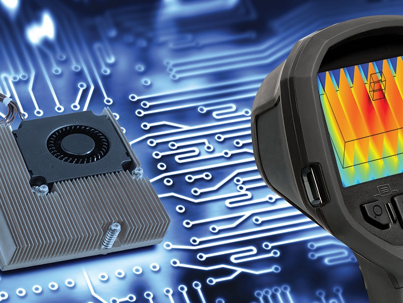
When electrical engineers mention the term "power management", most people think of MOS tubes, converters, transformers, etc. Actually, power management is much more than that. The power supply will heat up when working, and the continuous temperature rise will cause the change of performance, which may eventually lead to system failure. Heat also shortens component life and affects long-term reliability.
Therefore, power management also involves thermal management. There are two points of view about thermal management that are important to understand:
"Micro" | Problems
Individual components overheated due to excessive heat, but the rest of the system and housing were within temperature limits.
"Macro" | Question
The system overheats due to the accumulation of heat from multiple heat sources.
Engineers need to determine how much of the thermal management problem is micro and how much is macro, and to what extent the two are related.
Simply understood, a heating component, even if the temperature rises beyond its allowable limit and causes the whole system to warm up, does not necessarily mean that the whole system is overheating, but the excess heat generated by the component must be dissipated.
So where does the heat go?
It can be distributed to the adjacent parts of the system and chassis, or to the outside of the chassis (This is possible only when the temperature outside is lower than that inside).
Thermal management solutions
Heat management follows the fundamental principles of physics and there are three ways heat can be transferred: radiation, conduction and convection.
For most electronic systems, the desired cooling is achieved by first moving the heat away from the developing heat source by conduction, and then transferring it elsewhere by convection. Thermal design requires a combination of thermal management hardware to effectively achieve the required conduction and convection.
The most commonly used cooling elements are three: radiator, heat pipe and fan.
Radiators and heat pipes are passive cooling systems that require no power supply, while fans are active forced air cooling systems.
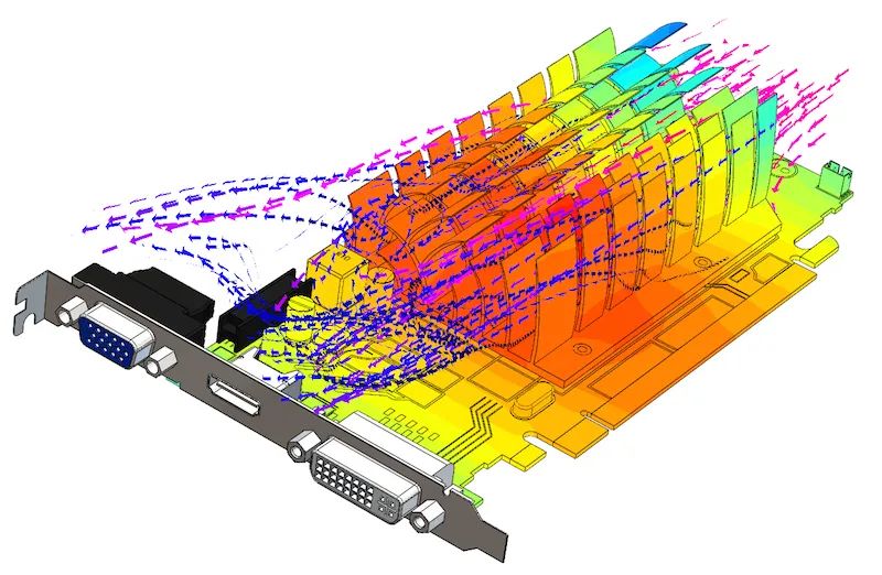
Radiator
Radiators are aluminum or copper structures that take heat from a heat source by conduction and transfer it to an air stream (in some cases, water or other liquid) for convection.
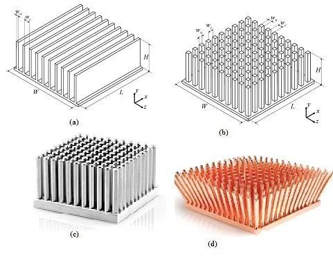
Various types of radiators
Heat sinks come in thousands of sizes and shapes, ranging from small stamped metal fins connected to individual transistors to large extrusions with many fins (fingers) that can intercept convective air flow and transfer heat to that flow. Heat sinks have the advantages of no moving parts, running costs, failure modes, etc. Once the radiator is connected to the heat source, convection occurs naturally as the warm air rises, initiating and continuing airflow.
Although radiators are easy to use, there are some drawbacks:
1, large heat transfer radiator volume, high cost, weight, and must be placed correctly, will affect or limit the physical layout of the circuit board;
2, the fin may be blocked by dust in the airflow, reducing the efficiency;
3. It must be correctly connected to the heat source to make the heat flow smoothly from the heat source to the radiator.
Heat pipe
It is another important component of the thermal management suite that transfers heat from point A to point B without any form of active coercion.
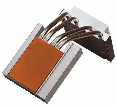
It contains a sealed metal tube with a sintered core and working fluid, which does not act as a heat sink itself but acts to absorb heat from the heat source and transfer it to a cooler area.
Heat pipes can be used when there is not enough space for a radiator near the heat source or when there is insufficient airflow. Heat pipes are efficient and can transfer heat from the source to a more manageable location.
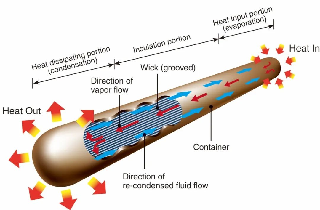
The working principle is simple and ingenious:
Working principle:
The heat source converts the working fluid into steam in the sealed tube, and the steam carries the heat to the cooler end of the heat pipe. At this end, the vapor condenses into a liquid and gives off heat, and the fluid returns to the hotter end. This gas-liquid transformation process is continuous and driven only by the temperature difference between the cold and hot ends. Connecting a radiator or other cooling device at the cold end can solve the heat dissipation problem of local hot spot where the air flow is blocked.
Air fan
It's the first step in moving away from passive radiators and heat pipes and toward forced air cooling with active cooling, but the fan has its headaches:
1, increase the cost, need space, increase the system noise;
2, prone to failure, energy consumption and affect the efficiency of the whole system.
But in many cases, especially when the airflow path is curved, vertical, or blocked, they are often the only way to get enough airflow.
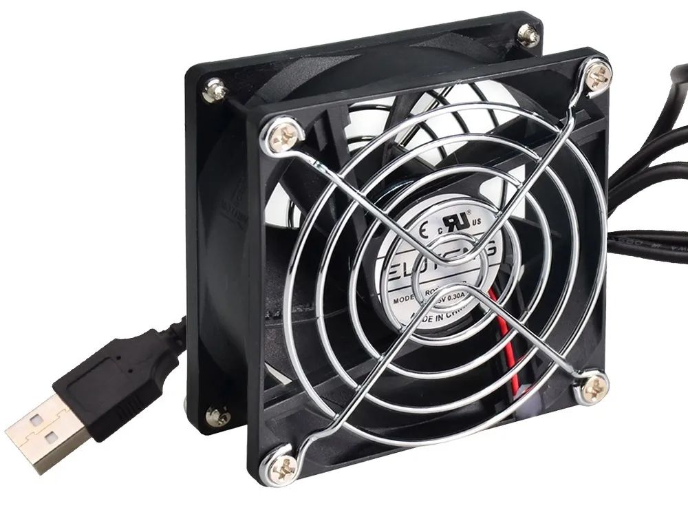
The key parameter that defines a fan's capability is the flow rate per unit length or volume of air per minute.
But physical size is an issue: a large fan at a low speed can produce the same airflow as a small fan at a high speed, so there is a trade-off between size and speed.
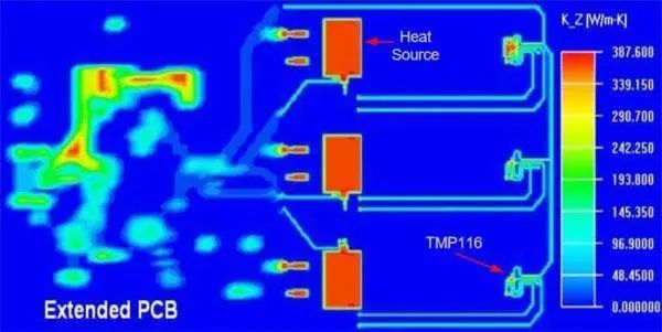
Modeling and comprehensive simulation
Separate passive systems are larger but more reliable and efficient, and fans can work when passive cooling alone is not possible. Which system to choose for cooling is often a difficult decision. This is where modeling and simulation is needed to determine how much cool air is needed and how to achieve cooling, which is critical to efficient thermal management strategies.
For miniature models, heat sources and their heat flow paths are characterized by their thermal resistance, which is determined by the materials, mass and size used.
Modeling how heat flows out of a heat source is also the first step in evaluating components that can cause thermal accidents due to their own heat loss.
Device suppliers such as high-heat dissipating IC, MOSFET, and IGBT often provide thermal models that provide details of the thermal path from the heat source to the device surface.
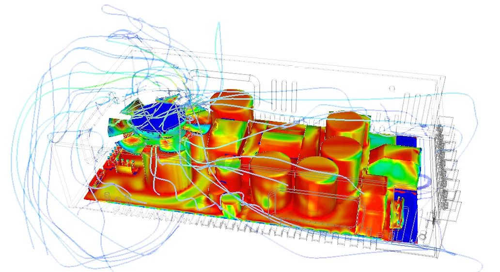
Once the thermal load of each component is known, the next step is modeling at the macro level, which is both simple and complex: air flows from various heat sources are adjusted to keep their temperatures below permissible limits; Basic calculations are made using air temperature, unforced airflow availability, fan air flow, and other factors to get a rough idea of the temperature situation. This is followed by a more complex modeling of the entire product and its package using the model and location of each heat source, the PC board, the surface of the case, and other factors.
Finally, modeling solves two problems:
1. The problem of peak and average dissipation.
For example, a steady-state component with a heat dissipation duration of 1W has different thermal effects than a device with a heat dissipation of 10W but a 10% intermittent duty ratio. In other words, if the average heat dissipation is the same, the related heat mass and heat flux will produce different heat distributions. Most CFD applications can combine static and dynamic analysis.
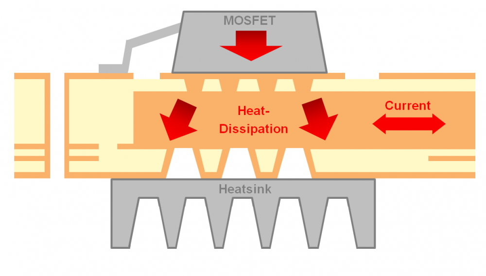
2. Imperfection of physical connections between the surfaces of components and miniature models
For example, the physical connection between the top of the IC package and the heat sink. If the connections are slightly spaced, the thermal resistance of the path will increase and thermal spacers will need to be filled at the contact surface to enhance the thermal conductivity of the path.
Thermal management can reduce the temperature of the components in the power supply and the internal environment, which can extend the service life of the product and improve the reliability. But thermal management is an integrated concept that, when broken down to its minutiae, is a huge topic. It involves trade-offs in terms of size, power, efficiency, weight, reliability, and cost. Project priorities and constraints must be evaluated.

